IFC_Bridge
Funding: Federal Ministry of Transport (BMVI)
Realization: André Borrmann (as Technical Lead), bSI IFC-Bridge Project Team
Documentation: Detailed Report
Overview
Industry Foundation Classes(IFC) is a comprehensive data model allowing the detailed geometric and semantic description of buildings and is widely used as a software vendor-independent BIM data exchange standard. It is developed by the international non-profit organization buildingSMART and has been published as ISO standard 16739 since 2013. Up to version IFC4, the IFC standard was mainly focused on buildings. However, due to increasing international demand, a substantial extension of the standard to support infrastructure facilities is being carried out.
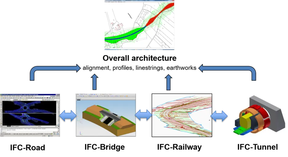
To this end, the Infrastructure Room, a subdivision of buildingSMART International (bSI) with its own steering committee, was founded in 2013. It developed a roadmap and started a number of projects to develop the necessary extensions. The first project was IFC-Alignment, which defined extensions for describing the alignment of linear infrastructure assets (Liebich et al. 2017). On this basis, the IFC Infra Overall Architecture project was conducted in order to specify general principles to be followed by all Infrastructure extension projects. On top of that, the projects IFC-Bridge, IFC-Rail, IFC-Road and IFC-Tunnel have been initiated.

In response to the urgent demand of international infrastructure stakeholders for extending IFC for bridges, the standard development project was initiated by Infra Room as a fast-track project with a duration of 2 years. It started in January 2017 and was completed with a slight delay in April 2019. Due to the limited time and resources available, it was essential that the project focused on "low hanging" fruits; i.e. selecting use cases to be supported that bring the most value to the future users of the standard. The IfcBridge extension project followed the formal project execution guidelines of bSI that came into effect in 2015 (buildingSMART International 2015). They define two essential components to be implemented by each project:
- the organizational structure,
- the development process.
The development process
As demanded by bSI guidelines, the IFC-Bridge project implemented the following development phases:
- Requirements Analysis
- Taxonomy Analysis
- Conceptual model development
- IFC schema extension proposal (draft)
- Validation
- IFC schema extension proposal (final)
- Formal acceptance
Use cases covered
The project team performed an in-depth analysis of the use cases for a software vendor-independent bridge data exchange format in order to identify those that are supposed to be supported by the extension, and those that are considered out-of-scope. The analysis included specifying the sending and the receiving application, rough descriptions of the required geometry representations and the semantic data as well as an assessment of the complexity of the realization of the required data structure. In addition, the priority of individual use case support was identified through intense consulting of the expert panel.
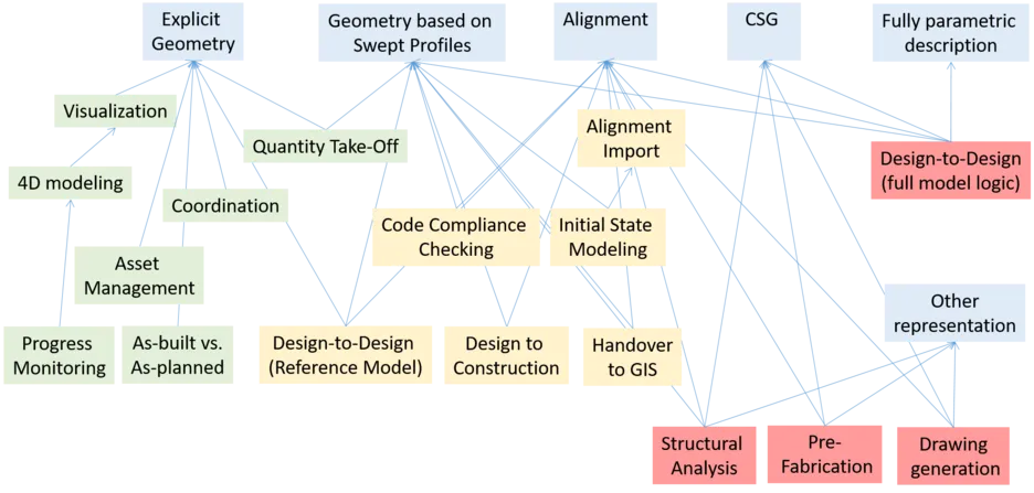
Based on a careful analysis of the benefits of the individual use cases and the complexity and effort involved with defining the necessary data structures, the project team decided to prioritize the following use cases for explicit consideration when designing the IFC-Bridge extension:
- Initial State Modeling
- Import of major road / railway parameters
- Technical Visualization
- Coordination / Collison Detection
- 4D Construction Sequence Modeling
- Quantity Take-Off
- Progress Monitoring
- As-built vs. as-planned comparison
- Handover to asset management
- Handover to GIS for spatial analysis
- Design to design (reference model)
Due to overly high complexity, the following use cases were marked as out of scope of the fast-track project:
- Design to Design (Full model logic)
- Structural analysis
- Code Compliance Checking
- Drawing generation and exchange
- Prefabrication and manufacturing
The full design-to-design use case, which incorporates the model’s design logic (Ji et al. 2013), was excluded as it would require a major effort from both bSI in defining the necessary data structures and from software vendors in correctly implementing them. It was emphasized that the exclusion from the fast-track project does not mean that these use cases will not be addressed by future IFC-Bridge extensions.

Conceptual model development
In the next step, the conceptual model was developed. The conceptual model describes the IFC extensions mostly by using UML diagrams in combination with documentation text. As opposed to the approach taken by OGC, the bSI conceptual model takes the particularities of the existing IFC data model into account and describes, for example, new sub-classes as refinements to existing IFC classes. It also defines attributes and properties where appropriate. The major part of the conceptual model is depicted in UML in Figure 4.
It is very important to note that the IFC-Bridge project implemented the guidelines of the Infra Overall Architecture Project (Borrmann et al. 2017), which demand to keep the number of new entities to minimum and instead provide a maximum of re-usage of existing classes. A good example is the Wing Wall of an Abutment. It is not necessary to define a new class for it, instead the existing IfcWall can be used. However, it may be appropriate to extend the enumeration of the predefined types of an entity. Where necessary, the documentation was modified to include bridge concepts.
Due to the principle described above, the resulting conceptual model only adds a minimum amount of new entities. At the same time however, a large number of new predefined types for a variety of entities were introduced. Figure 5 shows these extensions.
Spatial elements
In the IFC model, spatial structure elements are applied to capture the spatial hierarchy of a project. As the prior IFC data model was limited to buildings, a significant extension was necessary. A general concept applicable also for other types of facilities was implemented by means of the entities IfcFacility and IfcFacilityPart.
The new spatial entities defined are:
- IfcFacility – subtype of IfcSpatialStructureElement
- IfcFacilityPart – subtype of IfcSpatialStructureElement
- IfcBridge – subtype of IfcFacility
- IfcBridgePart – subtype of IfcFacilityPart
Physical elements
The majority of physical elements of bridges can be described by means of the existing entities. The following new entities were defined to describe bridge-specific physical elements:
- IfcBearing – subtype of IfcBuildingElement
- IfcDeepFoundation – subtype of IfcBuildingElement
- IfcCaissonFoundation – subtype of IfcDeepFoundation
- IfcVibrationDamper – subtype of IfcVibrationDamper
- IfcTendonConduit – subtype of IfcReinforcingElement
Systems
New predefined types were defined for the existing entity IfcBuildingSystem in order to support a more appropriate representation of reinforcement and the prestressing system:
- REINFORCING
- PRESTRESSING
Positioning
The new relationship IfcRelPositions (subtype of IfcRelConnects) may be used to relate IfcObjects for which placement or geometry is defined relative to alignments (or grids).
The presence of such relationship allows for modification scenarios where alignments may change and dependent objects may then have placement and geometry adjusted accordingly. Such relationship is similar in functionality as IfcRelConnectsPathElements, where the adjustment of a wall, beam, or column can then be propagated to connected walls, beams, or columns.
Proposed IFC schema extension (draft)
Based on the conceptual model, the actual extension of the IFC schema was realized. This was done by defining the corresponding EXPRESS schema. From the EXPRESS schema, all other data schemas supported by bSI are derived (ifcXML, ifcOWL). In addition, a comprehensive HTML documentation is generated. With respect to the latter, the project team created the documentation for new entities and updated those parts of the existing documentation where semantics were altered or extended.
The draft extension was published on bSI Forums for direct feedback from the international community.
Validation
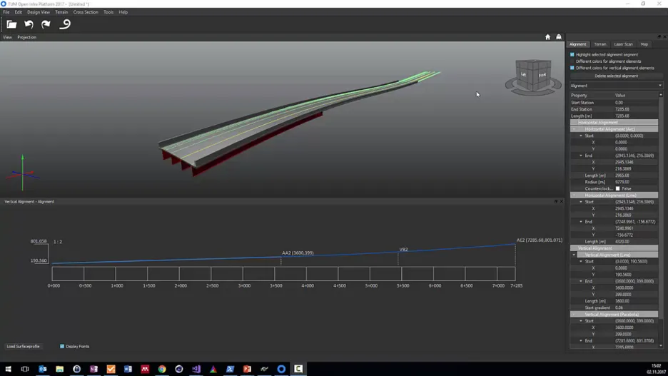
To avoid ambiguities and identify deficiencies, the extension was validated through prototypical implementation in two IFC applications and several tests to confirm successful data exchange between these two applications. One of the employed applications is TUM Open Infra Platform (Amann et al. 2016), the other one is eveBIM by CSTB.

IFC Schema extension (final)
For the publication of the final version of the schema extension, the bugs and ambiguities identified in the course of the validation phase were fixed. In addition, feedback from the international community was taken into account.
The fast-track standardization project was finished in March 2019. It is followed by a deployment project where interested software vendors are invited to join a coordinated early implementation effort. In the frame of the project, the software vendors are receiving intensive support and gain the opportunity to provide direct feedback on the standard. If major deficiencies are detected in this process, the standard will be revised accordingly.
After successful completion, the official bSI standards adoption process is performed. Upon approval of the standards committee, the extension becomes the official IFC 4.2 candidate standard and is subsequently set for vote by the national or regional chapters of buildingSMART International. If accepted, the standard will become the official IFC 4.2 release.
If requested by the community, a further extension of the standard with additional bridge-specific elements can be realized in a future IFC-Bridge 2.0 project. This may involve more advanced geometric representations to capture the parametrics of bridge design and enable their exchange between different design packages (Ji et al. 2013).
References
Amann, J., Schöttl, F., Singer, D., Kern, M., Widner, A., Geisler, P., Below, D., Hecht, H., Gupta, N., Mustafa, A., Markič, S. & Borrmann, A. (2016), ‘TUM Open Infra Platform 2017’. URL: https://www.cms.bgu.tum.de/oip
Borrmann, A., Amann, J., Chipman, T., Hyvärinen, J., Liebich, T., Muhič, S., Mol, L., Plume, J. & Scarponcini, P. (2017), ‘IFC Infra Overall Architecture Project: Documentation and Guidelines’, https://buildingsmart.org/wp-content/uploads/2017/07/08_bSI_OverallArchitecure_Guidelines_final.pdf
Borrmann, A., Beetz, J., Koch, C., Liebich, T. & Muhic, S. (2018), Industry foundation classes: A standardized data model for the vendor-neutral exchange of digital building models, in A. Borrmann, M. König, C. Koch & J. Beetz, eds, ‘Building Information Modeling’, Springer.
Borrmann, André; Muhic, Sergej; Hyvarinen, Juha; Chipman, Tim; Jaud, Stefan; Castaing, Christophe; Dumoulin, Claude; Liebich, Thomas; Mol, Laura: The IFC-Bridge project - Extending the IFC standard to enable high-quality exchange of bridge information models, In: Proceedings of the 2019 European Conference for Computing in Construction, 2019
buildingSMART International (2015), bSI Standards Process. URL: https://www.buildingsmart.org/standards/standardsprocess/
Castaing, C., Borrmann, A., Benning, P., Dumoulin, C., Chipman, T., Hyvaerinen, J., Liebich, T., Markic, S., Mol, L., Muhic, S., Moon, H., Myllymaki, H., Suo, N., Song, S., Shanding, Ai an Siming, L., Yi, Z., Yabuki, N. & Zhao, F. (2018), IfcBridge requirements analysis report, Technical report, buildingSMART International.
Hüthwohl, P., Brilakis, I., Borrmann, A. & Sacks, R. (2018), ‘Integrating RC Bridge Defect Information into BIM Models’, Journal of Computing in Civil Engineering 32(3), 04018013.
Ji, Y., Borrmann, A., Beetz, J. & Obergrießer, M. (2013), ‘Exchange of Parametric bridge Models using a Neutral Data Format’, Journal of Computing in Civil Engineering ASCE 27(6), 593–606.
Laakso, M. & Kiviniemi, A. (2012), ‘The IFC standard: A review of History, development, and standardization, Information Technology’, 17(9), 134–161.
Liebich, T., Amann, J., Borrmann, A., Chipman, T., Hyvärinen, J., Muhič, S., Mol, L., Plume, J. & Scarponcini, P. (2017), ‘IFC Alignment 1.1 Project, IFC Schema Extension Proposal’.
Sacks, R., Kedar, A., Borrmann, A., Ma, L., Brilakis, I., Hüthwohl, P., Daum, S., Kattel, U., Yosef, R., Liebich, T., Barutcu, B. E. & Muhic, S. (2018), ‘Seebridge as next generation bridge inspection: Overview, information delivery manual and model view definition’, Automation in Construction 90, 134–145.