Motivation
The design of architectural or engineering structures is highly complex, since normally several actors are involved in this iterative and interdisciplinary design process. Problems emerge often due to the use of different models for the same structure. From this arises the idea of a unified design (CAD) and analysis (FE) environment with a common model for the whole design cycle. This is aggravated by the fact that construc- tion processes have to deal with a manifold of nonlinearities (e.g. geometrically, material) and dependencies in the sequence.
Construction Stages
In order to depict a whole building process, all necessary components have to be developed and implemented. Initial deformations and stresses are an essential feature. The choice of how the previous stages are considered influences the results of the actual step. Hence, this aspect has to be discussed and taken into account when modeling processes. The sequence of steps is important when simulating nonlinear processes and single steps cannot be computed separately. A management for storing and passing the data of all steps has to be created.
Simulation Stages of the Pringle

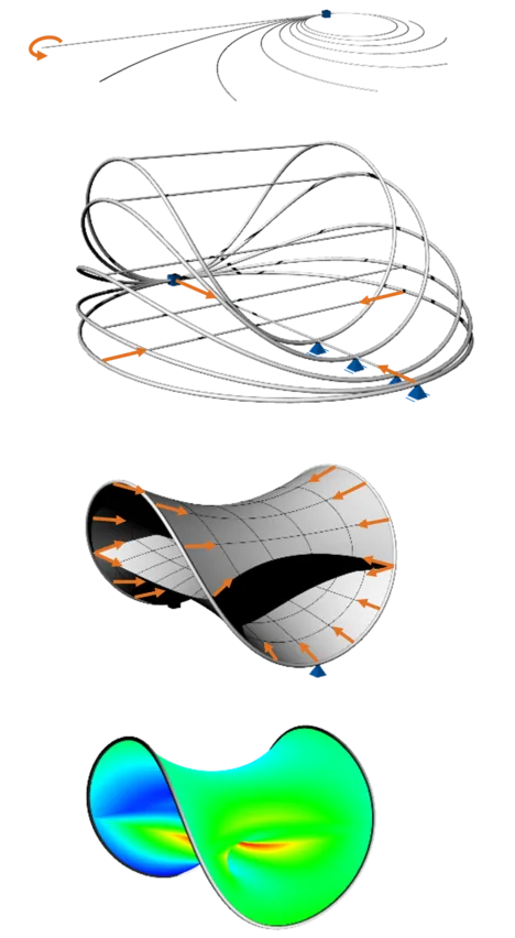
In the following, a bending-active structure is chosen by way of illustration. The stiffness of bending-active structures results from the assembling of nonlinearly deformed and prestressed elements in a determined sequence. Hence, the final result is strongly dependent on every stage and cannot directly be computed and evaluated. The exemplary construction process of a structure called Pringle consists of the following simulation and modeling steps:
a) The edge beam, which will be supporting the membrane, has to be bent to a circle by e.g. a bending moment at the tip of the cantilever.
b) The ends of the edge beam have to be coupled. Two cables are added and coupled to the beam by a weak boundary condition. An increasing prestressing of the cables forms the edge beam into the „Pringle“-form.
c) The cables are removed. The results of b) give the border for sketching in the initial surface of the prestressed membrane for the formfinding. The edge beam constitutes a soft support.
d) The formfound structure can be used for further analysis like for the simulation of wind loads.
Plug-In "Kiwi3d"
The design and engineering process is often restricted by time. Parametric design is a feature which allows you to vary some of the input parameters of the model and automatically derive the changes in the output structure. Currently, it is mainly used for geometrical or mechanically approximated features. Using our own developed plug-in Kiwi3d in Grasshopper®, one can parametrize a construction process with several simulation steps in one script. By changing an input parameter all consecutive steps until the final structure are adapted. A broad, mechanically correct parameter study of the final design is enabled and the solution quality is possibly augmented, since more variations can be studied in less time.